Using a relay with the ESP8266 is a great way to control AC household appliances remotely. This tutorial explains how to control a relay module with the ESP8266 NodeMCU. We’ll take a look at how a relay module works, how to connect the relay to the ESP8266 and build a web server to control a relay remotely (or as many relays as you want).
Introducing Relays
A relay is an electrically operated switch and like any other switch, it that can be turned on or off, letting the current go through or not. It can be controlled with low voltages, like the 3.3V provided by the ESP8266 GPIOs and allows us to control high voltages like 12V, 24V or mains voltage (230V in Europe and 120V in the US).
1, 2, 4, 8, 16 Channels Relay Modules
There are different relay modules with a different number of channels. You can find relay modules with one, two, four, eight and even sixteen channels. The number of channels determines the number of outputs we’ll be able to control.

There are relay modules whose electromagnet can be powered by 5V and with 3.3V. Both can be used with the ESP8266 – you can either use the Vin pin (that provides 5V) or the 3.3V pin.
Additionally, some come with built-in optocoupler that add an extra “layer” of protection, optically isolating the ESP8266 from the relay circuit.
Get a relay module:
- 5V 2-channel relay module (with optocoupler)
- 5V 1-channel relay module (with optocoupler)
- 5V 8-channel relay module (with optocoupler)
- 5V 16-channel relay module (with optocoupler)
- 3.3V 1-channel relay module (with optocoupler)
Relay Pinout
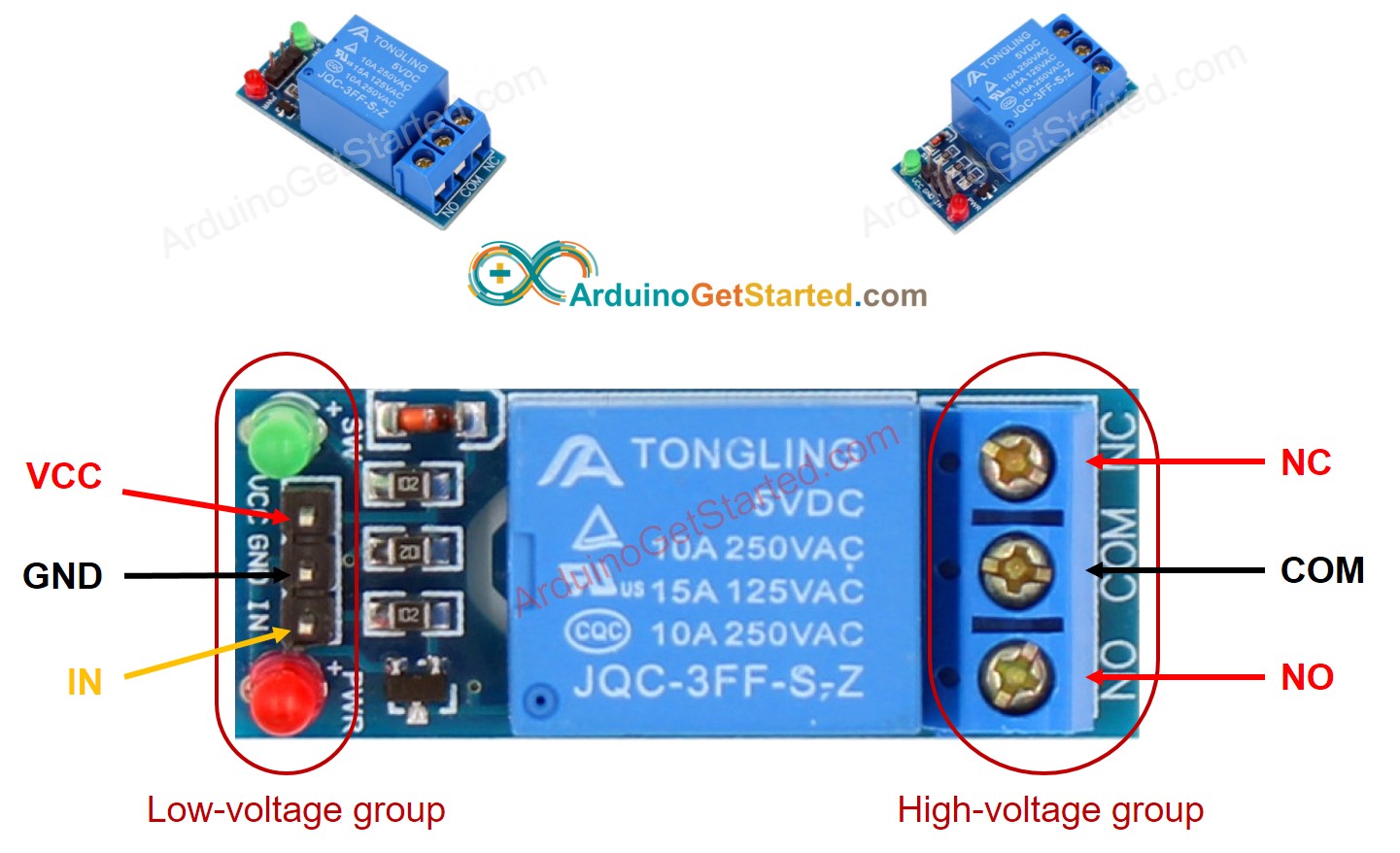
For demonstration purposes, let’s take a look at the pinout of a 2-channel relay module. Using a relay module with a different number of channels is similar.

The two connectors (with three sockets each) on the left side of the relay module connect high voltage, and the pins on the right side (low-voltage) connect to the ESP8266 GPIOs.
Mains Voltage Connections

The relay module shown in the previous photo has two connectors, each with three sockets: common (COM), normally closed (NC), and normally open (NO).
- COM: connect the current you want to control (mains voltage).
- NC (Normally Closed): the normally closed configuration is used when you want the relay to be closed by default. The NC are COM pins are connected, meaning the current is flowing unless you send a signal from the ESP8266 to the relay module to open the circuit and stop the current flow.
- NO (Normally Open): the normally open configuration works the other way around: there is no connection between the NO and COM pins, so the circuit is broken unless you send a signal from the ESP8266 to close the circuit.
Control Pins

The low-voltage side has a set of four pins and a set of three pins. The first set consists of VCC and GND to power up the module, and input 1 (IN1) and input 2 (IN2) to control the bottom and top relays, respectively.
If your relay module only has one channel, you’ll have just one IN pin. If you have four channels, you’ll have four IN pins, and so on.
The signal you send to the IN pins, determines whether the relay is active or not. The relay is triggered when the input goes below about 2V. This means that you’ll have the following scenarios:
- Normally Closed configuration (NC):
- HIGH signal – current is flowing
- LOW signal – current is not flowing
- Normally Open configuration (NO):
- HIGH signal – current is not flowing
- LOW signal – current is flowing
You should use a normally closed configuration when the current should be flowing most of the times, and you only want to stop it occasionally.
Use a normally open configuration when you want the current to flow occasionally (for example, turn on a lamp occasionally).
Power Supply Selection

With the jumper cap on, the VCC and JD-VCC pins are connected. That means the relay electromagnet is directly powered from the ESP8266 power pin, so the relay module and the ESP8266 circuits are not physically isolated from each other.
Without the jumper cap, you need to provide an independent power source to power up the relay’s electromagnet through the JD-VCC pin. That configuration physically isolates the relays from the ESP8266 with the module’s built-in optocoupler, which prevents damage to the ESP8266 in case of electrical spikes.
ESP8266 Safest Pins to Use with Relays
Some ESP8266 pins output a 3.3V signal when the ESP8266 boots. This may be problematic if you have relays or other peripherals connected to those GPIOs.
Additionally, some pins must be pulled HIGH or LOW in order to boot the ESP8266.
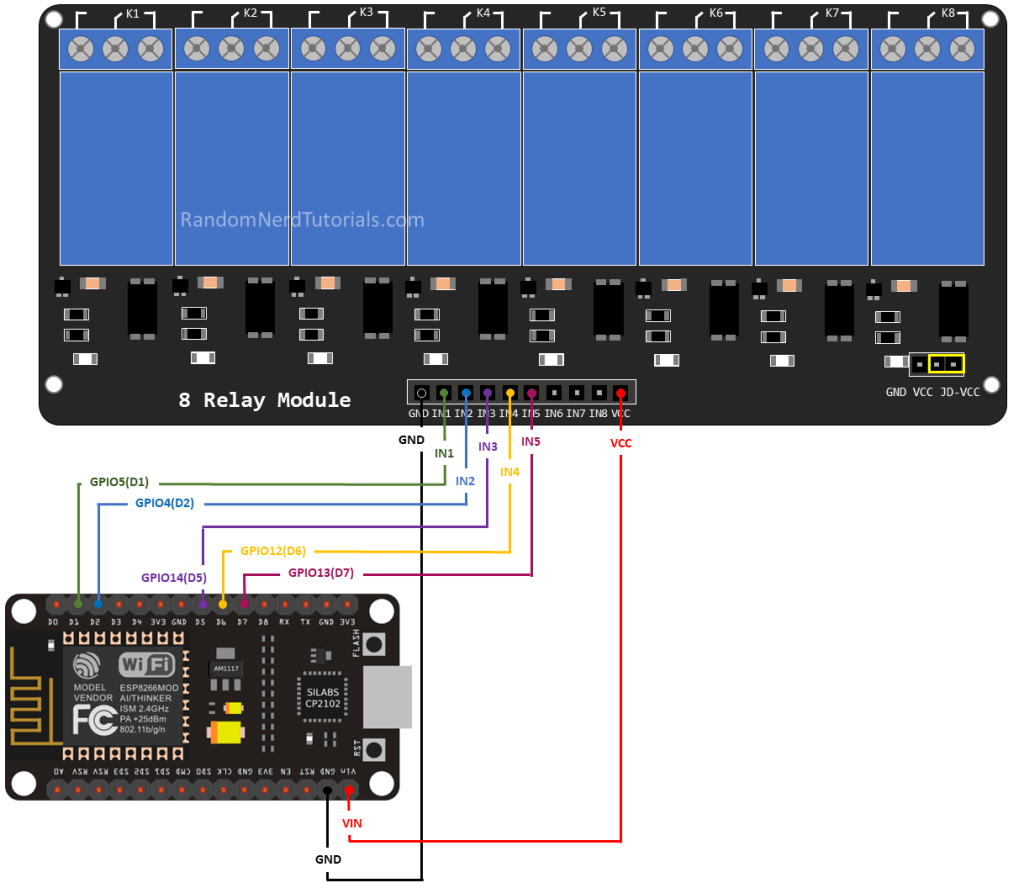
Taking this into account, the safest ESP8266 pins to use with relays are: GPIO 5, GPIO 4, GPIO 14, GPIO 12 and GPIO 13.
Wiring a Relay Module to the ESP8266 NodeMCU Board
Connect the relay module to the ESP8266 as shown in the following diagram. The diagram shows wiring for a 2-channel relay module, wiring a different number of channels is similar.
Warning: in this example, we’re dealing with mains voltage. Misuse can result in serious injuries. If you’re not familiar with mains voltage ask someone who is to help you out. While programming the ESP or wiring your circuit make sure everything is disconnected from mains voltage.
Alternatively, you can use a 12V power source to control 12V appliances.

In this example, we’re controlling a lamp. We just want to light up the lamp occasionally, so it is better to use a normally open configuration.
We’re connecting the IN1 pin to GPIO 5, you can use any other suitable GPIO. See ESP8266 GPIO Reference Guide.
Controlling a Relay Module with the ESP8266 NodeMCU – Arduino Sketch
The code to control a relay with the ESP8266 is as simple as controlling an LED or any other output. In this example, as we’re using a normally open configuration, we need to send a LOW signal to let the current flow, and a HIGH signal to stop the current flow.

/*********
  Rui Santos
  Complete project details at https://RandomNerdTutorials.com/esp8266-relay-module-ac-web-server/

  The above copyright notice and this permission notice shall be included in all
  copies or substantial portions of the Software.
*********/

const int relay = 5;

void setup() {
  Serial.begin(115200);
  pinMode(relay, OUTPUT);
}

void loop() {
  // Normally Open configuration, send LOW signal to let current flow
  // (if you're usong Normally Closed configuration send HIGH signal)
  digitalWrite(relay, LOW);
  Serial.println("Current Flowing");
  delay(5000);

  // Normally Open configuration, send HIGH signal stop current flow
  // (if you're usong Normally Closed configuration send LOW signal)
  digitalWrite(relay, HIGH);
  Serial.println("Current not Flowing");
  delay(5000);
}
linkhttps://randomnerdtutorials.com/esp8266-relay-module-ac-web-server/


int ledPin = D0;
int ledPin3 = D1;
int analogPin = A0;
int val = 0;
void setup() {
  pinMode(ledPin, OUTPUT);
  pinMode(ledPin3, OUTPUT);
  Serial.begin(115200);
}

void loop() {
  val = analogRead(analogPin);
  Serial.print("val = ");
  Serial.println(val);
  if (val > 800) {
    digitalWrite(ledPin, LOW);
    digitalWrite(ledPin3, HIGH);
  }
  else {
    digitalWrite(ledPin, HIGH);
    digitalWrite(ledPin3, LOW);
  }
  delay(3000);
}
int analogPin = A0;
int val = 0;
void setup() {
Serial.begin(115200);
}
void loop() {
val = analogRead(analogPin);
Serial.print("val = ");
Serial.println(val);
delay(3000);
}int Relay1 = D0;
void setup()
{
pinMode(Relay1, OUTPUT);
digitalWrite(Relay1, HIGH);
}
void loop()
{
digitalWrite(Relay1, LOW);
delay(3000); /
digitalWrite(Relay1, HIGH);
delay(3000);
}