Overview: What is ESP32CAM, how it works, What are its applications?
ESP32-CAM AI-Thinker is ESP32 based development board which is compact, small in size with integrated OV2640 camera. It also has few best features like GPIO pins to connect it with few modules, On board flashlight for camera picture quality and Micro SD card slot to read and save images and data.
The ESP32-CAM AI-Thinker board has integrated WiFi, Bluetooth and low-power BLE, with 2 high-performance 32-bit LX6 CPUs. It is designed in 7-stage pipeline architecture, with Hall sensor, temperature sensor and few other sensors on board. It’s main frequency setting ranges from 80MHz to 240MHz and computing power upto 600DIMPS(Dhrystone Million Instructions per Second). This board supports interfaces such as I2C/SPI/UART/PWM/ADC/DAC and camara units such as OV2640 and OV7670.
Fully compliant with WiFi 802.11b/g/n/e/i and Bluetooth 4.2 standards, it can be used as a master mode to build a standalone network controller or as a slave to other host MCUs to add network capabilities to existing devices.
It is suitable for smart home devices, industrial wireless control, wireless monitoring, QR codes identification, wireless positioning system signals, and other IoT applications. It is an ideal solution for prototype builds, and DIY projects.
ESP32-CAM pinout diagram:
Below is the image of ESP32-CAM AI-Thinker development board pinout

As you can see from the above image it has the support for 3.3v and 5Volts power supply input pins, Few GPIO pins, Tx and Rx pins, and few other pins.
As you can see from the above image it has the support for 3.3v and 5Volts power supply input pins, Few GPIO pins, Tx and Rx pins, and few other pins.
Add external antenna to ESP32-CAM to increase the range(Optional)
It has an inbuilt antenna at the top as you can see from the above image, If the distance from the router to the board increases the signal strength decreases, as a solution to increase the range it has a support to add external antenna with IPEX connector. It is very easy just get an external antenna online or from store and plug it to the slot given on the ESP32-CAM board and realign the resistor beside it as shown in the below image.

To attach an external antenna first desolder the resister carefully as it is very small and resolder it in the opposite position as in the above image. If you feel soldering the resistor again is hard then just connect the points with solder without resistor. It works as long as the points are connected.
ESP32-CAM on board antenna works good with in 10-15 meters range and sometimes it may disconnect so get an external antenna for strong and stable connectivity and range.
Note: ESP32-CAM AI-Thinker board does not have a display, microphone, motion sensors, battery connector, built-in programmer, grove connectors, or function buttons, so you need to find solutions to these if you need them.
Related article: Interfacing OLED display with ESP32
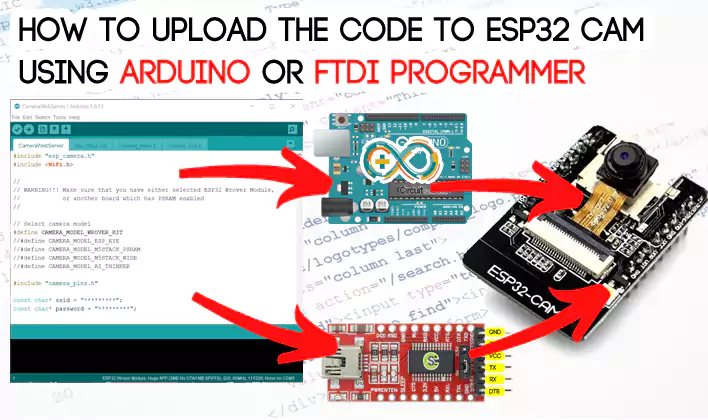
How to Upload the code to ESP32-CAM using Arduino UNO
As we already learnt ESP32-CAM doesn’t have an inbuilt programmer to upload the code directly to it using Arduino IDE, so in this method we are using Arduino UNO board, which works as a programmer to upload the code to ESP32-CAM module instead of using converters such as FTDI programmer. Follow the below detailed steps to do so.
Components required:
- ESP32CAM module
- Arduino UNO
- Few connecting wires.
Circuit Diagram to interface ESP32CAM with Arduino UNO
Connect the above required components according to the below circuit diagram.
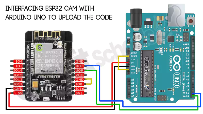
From the above schematic diagram you can see that there are two jumper cables connected one is for ESP32CAM connected between GND and IO0, and another is for Arduino UNO GND and RESET pins. ESP32CAM module is powered from the Arduino UNO 5v and GND pins connected to same on ESPCAM. The data transfer pins UOT and UOR from the ESP32CAM are connected to TX and RX pins of Arduino respectively.
Thats it for connections now you can connect the Arduino UNO board to PC and follow the below steps to upload the code.
Related post: Live stream with ESP32 camera module over internet with Face Recognition
Setting up Arduino IDE.
Download and install Arduino IDE on your PC, where Arduino UNO board is connected.
Now add ESP32 board manager by opening File -> Preferences and paste the below URL in the Additional boards manager URLs field.
https://dl.espressif.com/dl/package_esp32_index.json
https://raw.githubusercontent.com/espressif/arduino-esp32/gh-pages/package_esp32_index.json
Now open Tools -> Board:xxxxx -> ESP32 Arduino -> select : ESP32 Wrover module
Set the Tools menu settings as shown below
- Board: “ESP32 Wrover Module” >
- Upload Speed: “115200” >
- Flash Frequency: “80MHz” >
- Flash Mode: “Q10” >
- Partition Scheme: “Huge APP (3MB No OTA/1 MB SPIFFS)” >
- Core Debug Level: “None” >
- Port: “COMx’ > According to your port connection

Uploading the code: ESP32CAM webserver
As an example lets use the code from the ESP32 Examples library by opening File -> Examples -> ESP32 -> Camera -> CameraWebServer. An example ready made code will be loaded, you just need to change the WiFi credentials in the code and click on Upload button.

After clicking on upload icon you can see the connecting dots as the above image, when you see them press the RST(Reset button) on the board which leads to code upload, with in few seconds you will see the message “Done uploading” on status bar of Arduino IDE means code uploaded successfully.
Now remove the jumper connection between GPIO1(IO0) and GND on ESP32 CAM module. Open serial monitor and set the baud rate to the value which we mentioned in the code i.e., 115200 and press RST button on the ESP cam board.
Now you can see the IP address of the webserver from where we can access the ESP32 CAM features, camera etc. as shown in the serial monitor image below.
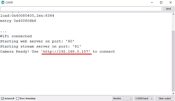
Now Open the address in a web browser to access the ESP32CAM dashboard.

How to Upload the code to ESP32-CAM using USB to TTL/FTDI programmer
In this method a special board is used to upload the code to ESP32 CAM named USB to TTL or FTDI converter. This boards will provide the connectivity between USB and UART interfaces. There are wide varieties of FTDI programmers are available with different output voltages like 3V, 5V.
In this method we are using FT232RL USB TO TTL Converter.
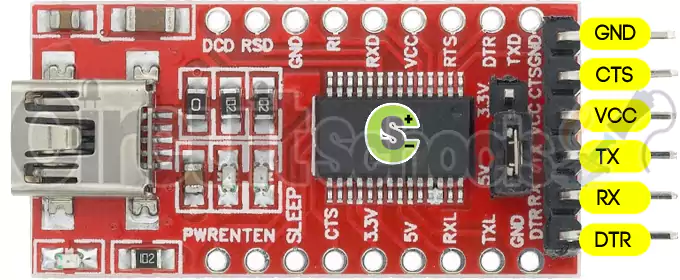
Features and Specifications of FT232RL USB TO TTL Converter
This section mentions some of the features and specifications of the FT232RL USB to TTL Converter:
- Operating Voltage: 5V/3.3V DC
- Connector: Mini USB
- Max Current Draw: 5V – 500mA; 3.3V – 50mA
- Data transfer rates from 300 baud to 3 Mbaud (RS422, RS485, RS232) at TTL levels
- Fully integrated 1024 bit EEPROM storing device descriptors and CBUS I/O configuration
- 128 byte receive buffer and 256 bytes transmit buffer
Components required:
- ESP32CAM module
- FTDI Programmer/USB to TTL programmer
- Few connecting wires.
Circuit Diagram to interface ESP32CAM with USB to TTL programmer
Connect the above required components according to the below circuit diagram.
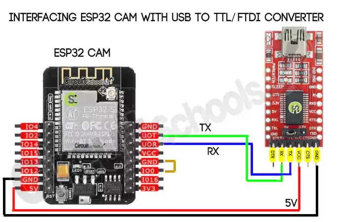
As you can see from the above schematic diagram GND and GPIO0 pins are connected with a jumper on ESPCAM board. ESPCAM board is powered from the VCC and GND from FTDI to 5V and GND respectively, The transfer and receive pins TX and RX pins from FTDI are connected to UOR and UOT pins of ESPCAM respectively.
Setting up Arduino IDE
This is same as the Above Arduino UNO method, Please refer the above method to setup Arduino IDE.
Upload and execute the Code:
This is same as the Above Arduino UNO method, Please refer the above method to setup Arduino IDE.
After uploading the code remove the jumper between GPIO0 and GND pins on ESPCAM.
Errors while uploading:
Failed to connect to ESP32: Timed out waiting for packet header
Solution: Check the wiring connections between the Arduino/FTDI programmer and ESP32CAM board, if everything is ok Press the RST button when dots are processing after clicking on upload icon.
Brownout detector was triggered
This error occurs for the following reasons: when the quality of the USB cable is poor, cable is very long for the data to reach, Voltage is not sufficient to ESP32 CAM board.
Solution: If there is voltage problem use external 5v power supply to power the ESP board as Arduino UNO sometimes cannot provide 5v , use short USB cable for data transfer.
#include "esp_camera.h"
#include <WiFi.h>

//
// WARNING!!! Make sure that you have either selected ESP32 Wrover Module,
//            or another board which has PSRAM enabled
//

// Select camera model
//#define CAMERA_MODEL_WROVER_KIT
//#define CAMERA_MODEL_ESP_EYE
//#define CAMERA_MODEL_M5STACK_PSRAM
//#define CAMERA_MODEL_M5STACK_WIDE
#define CAMERA_MODEL_AI_THINKER

#include "camera_pins.h"

const char* ssid = "aaaaaaa";
const char* password = "bbbbbbb";

void startCameraServer();

void setup() {
  Serial.begin(115200);
  Serial.setDebugOutput(true);
  Serial.println();

  camera_config_t config;
  config.ledc_channel = LEDC_CHANNEL_0;
  config.ledc_timer = LEDC_TIMER_0;
  config.pin_d0 = Y2_GPIO_NUM;
  config.pin_d1 = Y3_GPIO_NUM;
  config.pin_d2 = Y4_GPIO_NUM;
  config.pin_d3 = Y5_GPIO_NUM;
  config.pin_d4 = Y6_GPIO_NUM;
  config.pin_d5 = Y7_GPIO_NUM;
  config.pin_d6 = Y8_GPIO_NUM;
  config.pin_d7 = Y9_GPIO_NUM;
  config.pin_xclk = XCLK_GPIO_NUM;
  config.pin_pclk = PCLK_GPIO_NUM;
  config.pin_vsync = VSYNC_GPIO_NUM;
  config.pin_href = HREF_GPIO_NUM;
  config.pin_sscb_sda = SIOD_GPIO_NUM;
  config.pin_sscb_scl = SIOC_GPIO_NUM;
  config.pin_pwdn = PWDN_GPIO_NUM;
  config.pin_reset = RESET_GPIO_NUM;
  config.xclk_freq_hz = 20000000;
  config.pixel_format = PIXFORMAT_JPEG;
  //init with high specs to pre-allocate larger buffers
  if(psramFound()){
    config.frame_size = FRAMESIZE_UXGA;
    config.jpeg_quality = 10;
    config.fb_count = 2;
  } else {
    config.frame_size = FRAMESIZE_SVGA;
    config.jpeg_quality = 12;
    config.fb_count = 1;
  }

#if defined(CAMERA_MODEL_ESP_EYE)
  pinMode(13, INPUT_PULLUP);
  pinMode(14, INPUT_PULLUP);
#endif

  // camera init
  esp_err_t err = esp_camera_init(&config);
  if (err != ESP_OK) {
    Serial.printf("Camera init failed with error 0x%x", err);
    return;
  }

  sensor_t * s = esp_camera_sensor_get();
  //initial sensors are flipped vertically and colors are a bit saturated
  if (s->id.PID == OV3660_PID) {
    s->set_vflip(s, 1);//flip it back
    s->set_brightness(s, 1);//up the blightness just a bit
    s->set_saturation(s, -2);//lower the saturation
  }
  //drop down frame size for higher initial frame rate
  s->set_framesize(s, FRAMESIZE_QVGA);

#if defined(CAMERA_MODEL_M5STACK_WIDE)
  s->set_vflip(s, 1);
  s->set_hmirror(s, 1);
#endif

  WiFi.begin(ssid, password);

  while (WiFi.status() != WL_CONNECTED) {
    delay(500);
    Serial.print(".");
  }
  Serial.println("");
  Serial.println("WiFi connected");

  startCameraServer();

  Serial.print("Camera Ready! Use 'http://");
  Serial.print(WiFi.localIP());
  Serial.println("' to connect");
}

void loop() {
  // put your main code here, to run repeatedly:
  delay(10000);
}
How to erase flash ESP32 memory
python
exit()
pip install esptool

python -m esptool --chip esp32 --port COM9 --baud 115200 --after hard_reset erase_flash

python -m esptool --port COM9 write_flash_status --non-volatile 0

python -m esptool --port COM9 erase_flash