Introduction
In This Project, You Learn Full Home Automation using blank App & NodeMcu(esp8266). This Project is the Most Common & Popular Project Across The Internet. Home Automation Mean We Controlled Home Light, Measuring the GAS Level, Measuring Temperature & humidity And Measuring the Water Tank Level.
In This Project, We are Measuring The 4 Parameter And Controlling the two applications. all possibilities will be done by wifi Through I mean the NodeMcu is InBult Wifi Controller. And When The Wifi is Connected to the NodeMcu We Control The Applications And Measuring The Parameter Anywhere in the World. All Data will Show in Blyank2.0 App.
Bill Of Materials
| S.N | Component Name | Quantity | Link To Buy |
| 1 | NodeMcu (esp8266) | 1 | |
| 2 | 16×4 LCD Display | 1 | |
| 3 | Ultrasonic Sensor | 1 | |
| 4 | MQ-2 Sensor | 1 | |
| 5 | DHT-22 Sensor | 1 | |
| 6 | 2-Channel Relay Module | 1 | |
| 7 | Buzzer | 1 | |
| 8 | Zero Pcb | 1 |
Block Diagram
The Block Diagram for The Project is Given Below. Using The Block Diagram We Just Decide on The Input And Output Components.
I Mean Which Sensor We Used on the Input Side Like DHT22 Sensor, Ultrasonic Sensor, or MQ-2 Sensor And Output Side We Used a 16×4 Lcd Display, and 2 Channel Relay Module To Turn ON/OFF The Home Application.

Circuit Diagram
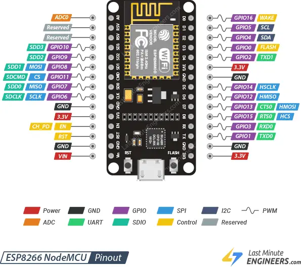
Now Will Discuss The Circuit Diagram Of The Project. We are ready to Decide on the INPUT/OUTPUT component in Block Diagram. Now I will Explain and Show The Pin Connected to The Sensor With NodeMcu.
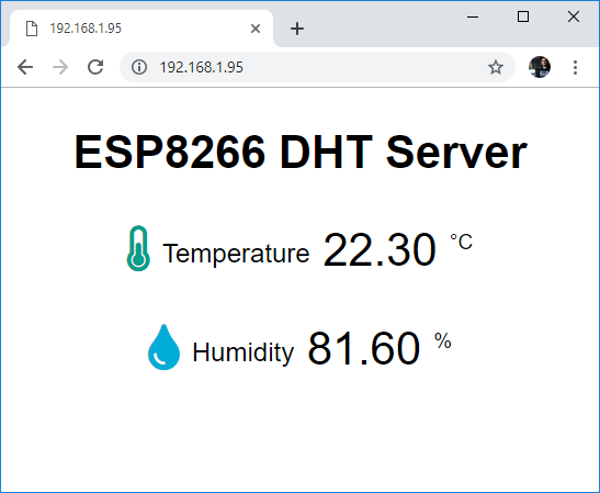
DHT-22 Sensor Will Providing The Digital Value That’s Why I connected to the digital PIN D3 PIN Of Nodemcu. And is given The Output in the Form Of Temperature And Humidity.
Ultrasonic Sensor They Will Also Be a Digital Sensor That’s Why I connected the PIN D6 and D5. I mean Trigger Pin Will Connected To PIN D6 And Echo Pin Will connect to PIN D5.
MQ-3 Sensor They Will Provide Digital Value And Analog Value. This Project is required the Analog Value That’s Why I connected the A0 PIN. In NodeMcu We Have Only One Analog Pin Not More Analog Pin.
2-Channel Relay Module Is an Output Device And When You Give a ‘0’ signal to The Input Then Relay Will On if you give a ‘1’ Then Really will OFF. And Output Side Of Relay We Just Connected the Home Applications They Work On AC Or Dc Voltage.
Relay Will Connected the PIN D7 And D8.
In This Project, I used The Small Buzzer And The Will Connected To PIN D0.

PCB Design

Setting Up Blynk App Application
Now It’s Time To set up Blynk Application.
If you Used To Laptop Then You are required To The Link https://blynk.cloud/dashboard/login Login to The Blynk Application.

- When You Login The Application We just Make A New Device If You Used Nodemcu just Type it Esp8266 And if you Used ESP32 Then Type It ESP32.

- Go To The Template Just Press The Your New Device And Edit It

Blynk Application
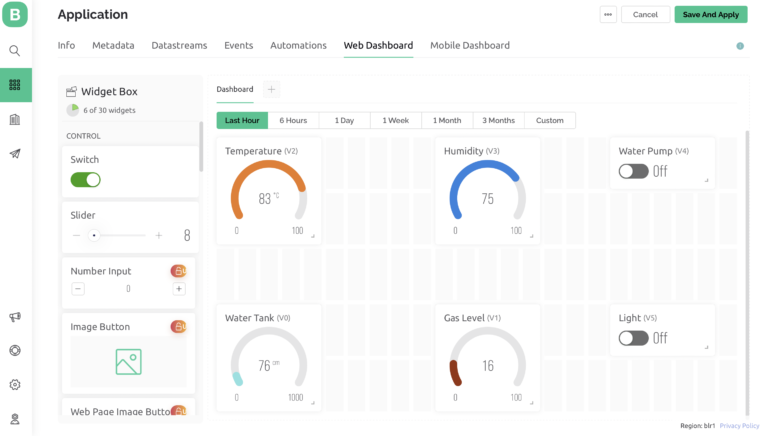
- You Just Add The Switch And Gauge And Define The Virtual Pin Like V0, V1…..

- When you have Done All Things You Just Save The File And Go To The MyDevice And Just Click The Your Template Then you See The Proper Output of The Application.

If You Used Mobile Application You Just go To our Playstore Search for it Blynk App and Download The Application.

Blynk ApplicationYou Just Sign In with the Same User Name And Password And Used The Application
Source Code / Program
When You Upload the Code To Your Controller Fist You Need To Change The Those Things.
Your Blynk App Auth Token
Wifi User Name
Wifi Password
char auth[] = "A45V5tHcYpxM7E_7DYth14iBEdUx6v";
char ssid[] = "prateek";
char pass[] = "justdoelectronics";
//Prtaeek
//www.justdoelectronics.com

#include <LiquidCrystal_I2C.h>
#define BLYNK_PRINT Serial
#include <ESP8266WiFi.h>
#include <BlynkSimpleEsp8266.h>
#include <DHT.h>

LiquidCrystal_I2C lcd(0x27, 16, 4);

char auth[] = "A45V5tHcYpxM7QbE_7DYth14iBEdUx6v";
char ssid[] = "prateeksingh";
char pass[] = "singh@@12345";

DHT DHT(D3, DHT22);
BlynkTimer timer;


#define Buzzer D0
#define MQ2 A0
#define trig D6
#define echo D5
#define relay1 D7
#define relay2 D8


void setup() {
  Serial.begin(115200);
  lcd.begin();
  lcd.backlight();
  pinMode(Buzzer, OUTPUT);
  pinMode(trig, OUTPUT);
  pinMode(echo, INPUT);
  pinMode(relay1, OUTPUT);
  pinMode(relay2, OUTPUT);
  digitalWrite(relay1, HIGH);
  digitalWrite(relay2, HIGH);
  Blynk.begin(auth, ssid, pass, "blynk.cloud", 80);
  DHT.begin();

  lcd.setCursor(0, 0);
  lcd.print("Welcome To ");
  lcd.setCursor(4, 1);
  lcd.print("Our Projects");
  delay(4000);
  lcd.clear();


  timer.setInterval(100L, gassensor);
  timer.setInterval(100L, DHT11sensor);
  timer.setInterval(100L, ultrasonic);
}


void DHT11sensor() {
  float h = DHT.readHumidity();
  float t = DHT.readTemperature();

  if (isnan(h) || isnan(t)) {
    Serial.println("Failed to read !");
    return;
  }
  Blynk.virtualWrite(V2, t);
  Blynk.virtualWrite(V3, h);

  lcd.setCursor(0, 1);
  lcd.print("Tem Level:");
  lcd.print(t);

  lcd.setCursor(-4, 2);
  lcd.print("Hum Level:");
  lcd.print(h);
}

void ultrasonic() {
  digitalWrite(trig, LOW);
  delayMicroseconds(4);
  digitalWrite(trig, HIGH);
  delayMicroseconds(10);
  digitalWrite(trig, LOW);
  long t = pulseIn(echo, HIGH);
  long cm = t / 29 / 2;
  Blynk.virtualWrite(V0, cm);

  lcd.setCursor(-4, 3);
  lcd.print("Water Level:");
  lcd.print(cm);
  lcd.print("  ");
}

void gassensor() {
  int value = analogRead(MQ2);
  Serial.println(value);
  value = map(value, 0, 1024, 0, 100);
  if (value <= 55) {
    digitalWrite(Buzzer, LOW);
  } else if (value > 70) {
    digitalWrite(Buzzer, HIGH);
  }
  Blynk.virtualWrite(V1, value);
  lcd.setCursor(0, 0);
  lcd.print("Gas Level:");
  lcd.print(" ");
  lcd.print(value);
}

BLYNK_WRITE(V5) {
  bool RelayOne = param.asInt();
  if (RelayOne == 1) {
    digitalWrite(relay1, LOW);
  } else {
    digitalWrite(relay1, HIGH);
  }
}


BLYNK_WRITE(V4) {
  bool RelayTwo = param.asInt();
  if (RelayTwo == 1) {
    digitalWrite(relay2, LOW);
  } else {
    digitalWrite(relay2, HIGH);
  }
}

void loop() {
  Blynk.run();
  timer.run();
}
Demo Of Project
This One Is The Final Hardware Of this Project

- Here We Just interfaced DHT-22 Sensor And You just See the Mobile Will Display The Temperature & Humidity.

- Now I just Interfacing the Ultrasonic Sensor And You Check Out The Output Of IN 16×4 Display And Mobile Applications.

- Now I just Interface MQ-2 Sensor And You Just Check Out The Output Of the MQ Sensor In the Display As well As the Mobile Application.
Link:https://justdoelectronics.com/home-automation-using-esp8266-blynk2-0-app
/*************************************************************
  Blynk is a platform with iOS and Android apps to control
  ESP32, Arduino, Raspberry Pi and the likes over the Internet.
  You can easily build mobile and web interfaces for any
  projects by simply dragging and dropping widgets.

    Downloads, docs, tutorials: https://www.blynk.io
    Sketch generator:           https://examples.blynk.cc
    Blynk community:            https://community.blynk.cc
    Follow us:                  https://www.fb.com/blynkapp
                                https://twitter.com/blynk_app

  Blynk library is licensed under MIT license
  This example code is in public domain.

 *************************************************************
  This example runs directly on ESP8266 chip.

  NOTE: This requires ESP8266 support package:
    https://github.com/esp8266/Arduino

  Please be sure to select the right ESP8266 module
  in the Tools -> Board menu!

  Change WiFi ssid, pass, and Blynk auth token to run :)
  Feel free to apply it to any other example. It's simple!
 *************************************************************/

/* Comment this out to disable prints and save space */
#define BLYNK_TEMPLATE_ID           "TMPL65xF_ujTl"
#define BLYNK_TEMPLATE_NAME         "Quickstart Template"
#define BLYNK_AUTH_TOKEN            "Hrr7CoFiiGAGOHrzXg6EG_NbLNwW-RNT"

#define BLYNK_PRINT Serial


/* Fill in information from Blynk Device Info here */
//#define BLYNK_TEMPLATE_ID           "TMPxxxxxx"
//#define BLYNK_TEMPLATE_NAME         "Device"
//#define BLYNK_AUTH_TOKEN            "YourAuthToken"


#include <ESP8266WiFi.h>
#include <BlynkSimpleEsp8266.h>

// Your WiFi credentials.
// Set password to "" for open networks.
char auth[] = BLYNK_AUTH_TOKEN;
char ssid[] = "sssss";
char pass[] = "xxxxx";


//Blynk.virtualWrite(V2, sensorVal);

//sensorData = analogRead(A0); // this is an example of reading sensor data


void setup()
{
  // Debug console
  pinMode(D1,OUTPUT);
  pinMode(D2,OUTPUT);
  //pinMode(sensorData,INPUT);

  Serial.begin(9600);

  Blynk.begin(auth, ssid, pass);
}

void loop()
{
  Blynk.run();


}

BLYNK_WRITE(V4)
{
  int pinValue = param.asInt();
  if(pinValue ==1)
  {
    digitalWrite(D1,LOW);
  }
  else
  {
  digitalWrite(D1,HIGH);
  }
}

BLYNK_WRITE(V3)
{
  int pinValue = param.asInt();
  if(pinValue ==1)
  {
    digitalWrite(D2,LOW);
  }
  else
  {
  digitalWrite(D2,HIGH);
  }
}