This tutorial of Robo India explains how to get address of i2c device connected to a NodeMCU using Arduino IDE.
Detailed Tutorial
1. Introduction:
2C bus is a means of connecting several peripheral input and output devices that support I2C on two wires. One of those wires is the DATA line called the SDA, whereas the other is the CLOCK line called the SCL. The information is sent on these two lines using what is called the I2C communication protocol.
This tutorial explains how to find attached i2c devices with NodeMCU. It also scans the address of each i2c device attached to the NodeMCU.
Here in the example an i2c LCD backpack is used to complete this tutorial, though this tutorial is general to get address of any i2c device connected to NodeMCU.
1.3 Hardware required
| S.No. | Item | Quantity |
| 1 | NodeMCU | 1 |
| 2 | Breadboard | 1 |
| 3 | i2c LCD Backpack | 1 |
| 4 | Jumper wire male to female | 4 |
2. Building Circuit

Addressing
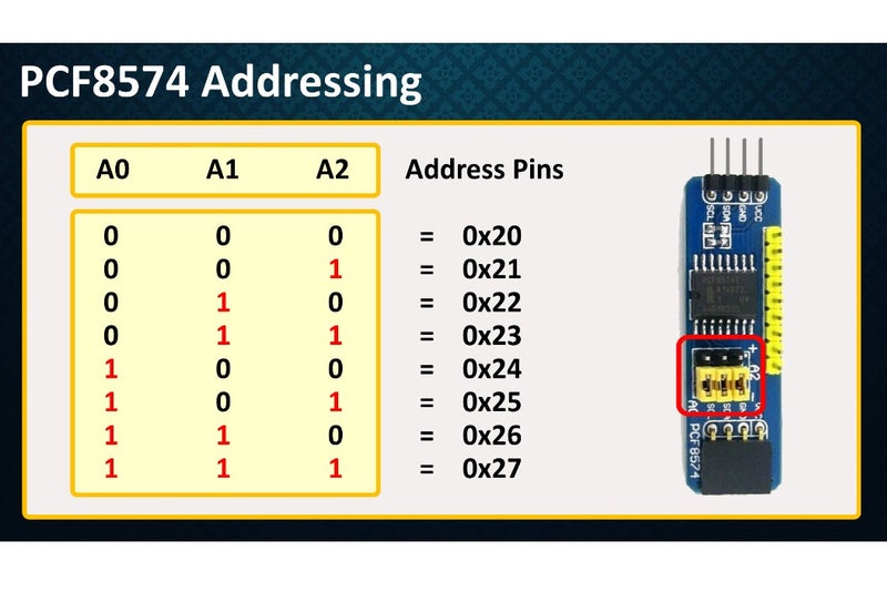
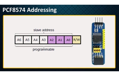
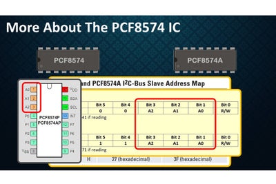
By connecting the three address bits A0, A1 and A2 to VIN or HIGH you can get different combination of the addresses.
This is how an address byte of the PCF8574 looks like. First 7-bits combine to form the slave address. The last bit of the slave address defines the operation (read or write) to be performed. When it is high (1), a read is selected, while a low (0) selects a write operation.
3. Programming:
Once the circuit part is done, NodeMCU is needed to be programmed. Here is the code to run this circuit on NodeMCU.
You may download this code (Arduino Sketch) from here.
// Robo India Tutorial
// Digital Input and Output on LED
// Hardware: NodeMCU

// Ref- Nick Gammon  http://www.gammon.com.au/forum/?id=10896
// I2C Scanner

#include <Wire.h>

void setup() {
  Serial.begin (9600);
  while (!Serial) // Waiting for serial connection
    {
    }

  Serial.println ();
  Serial.println ("I2C scanner. Scanning ...");
  byte count = 0;

  Wire.begin();
  for (byte i = 8; i < 120; i++)
  {
    Wire.beginTransmission (i);
    if (Wire.endTransmission () == 0)
      {
      Serial.print ("Found address: ");
      Serial.print (i, DEC);
      Serial.print (" (0x");
      Serial.print (i, HEX);
      Serial.println (")");
      count++;
      delay (1);  // maybe unneeded?
      } // end of good response
  } // end of for loop
  Serial.println ("Done.");
  Serial.print ("Found ");
  Serial.print (count, DEC);
  Serial.println (" device(s).");
}  // end of setup

void loop() {}
4. Output
Open serial monitor after uploading the code. The output of this sketch will be as shown below .The I2C address is highlighted. I2C address of our attached device is 0x3F.

If you have any query please write us at support@roboindia.com
Thanks and Regards
Content Development Team
Robo India
https://roboindia.com
https://www.instructables.com/PCF8574-GPIO-Extender-With-Arduino-and-NodeMCU/

