Project 011d 5V relay and DHT 11 21 22 sensor – Humidity or Temperature controlled relay
Basics: Project 011d
Project name: 5V relay and DHT 11 21 22 sensor – Humidity or Temperature controlled relay
Tags: Arduino, Arduino Uno, DHT11 21 22, Humidity and temperature module, 5V relay, Humidity controlled relay, Temperature controlled relay
Attachments: libraries1, library2 and sketch
WARNING – THIS PROJECT INVOLVES HIGH VOLTAGES THAT CAN CAUSE SERIOUS INJURY OR DEATH. PLEASE TAKE ALL NECESSARY PRECAUTIONS, AND TURN OFF ALL POWER TO A CIRCUIT BEFORE WORKING ON IT. WE ARE NOT RESPONSIBLE FOR ANY DAMAGE, INJURY, DEATH AND OTHER THINGS CAUSED BY THIS PROJECT IMPLEMENTATION.
In this project, you needed these parts :
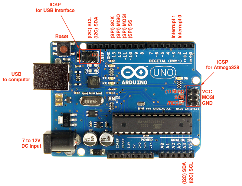
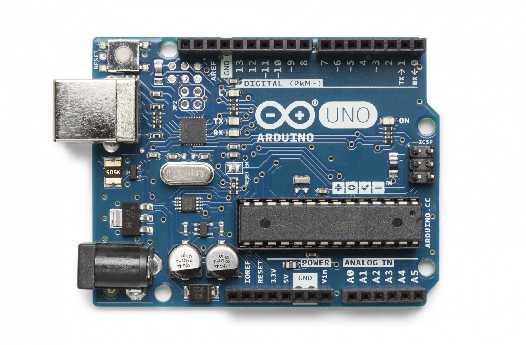
1.Aruduino Uno R3 (you can also use the other version of Arduino)
2.5V Relay module 1 pc

3.Arduino IDE ( you can download it from here )
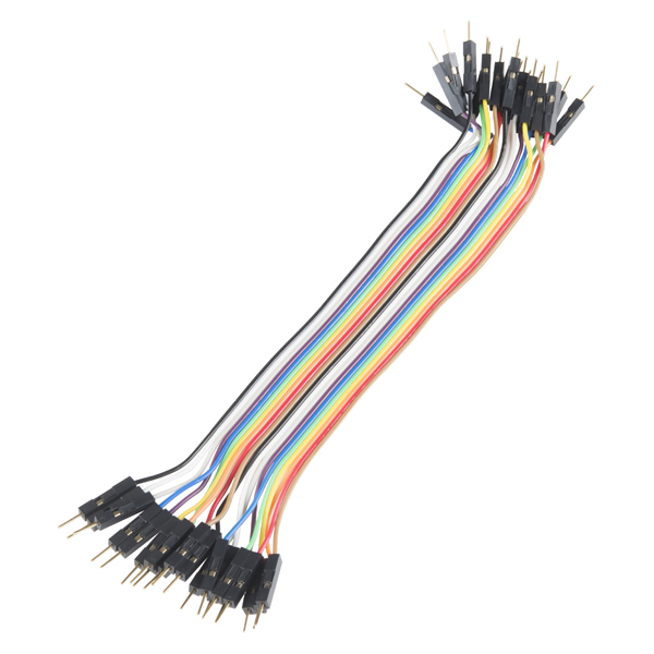
4.Jumper cables
5.Light bulb 60 W 220 V with connector 1pc

6.DHT11 or DHT21 or DHT22 – 1 pc

7.Resistor 1 KOm 1 pc
Understanding the Relay
You can read more about relay here.
You can find 5V relay module datasheet here.
Understanding DHT humidity and temperature sensor
We will use DHT11 module for this project. The DHT11 humidity and temperature sensor makes it really easy to add humidity and temperature data to your DIY electronics projects. It’s perfect for remote weather stations, home environmental control systems, and farm or garden monitoring systems.
Here are the ranges and accuracy of the DHT11:Humidity Range: 20-90% RHHumidity Accuracy: ±5% RHTemperature Range: 0-50 °CTemperature Accuracy: ±2% °COperating Voltage: 3V to 5.5V
- Humidity Range: 20-90% RH
- Humidity Accuracy: ±5% RH
- Temperature Range: 0-50 °C
- Temperature Accuracy: ±2% °C
- Operating Voltage: 3V to 5.5V
RELATIVE HUMIDITY
The DHT11 measures relative humidity. Relative humidity is the amount of water vapor in air vs. the saturation point of water vapor in air. At the saturation point, water vapor starts to condense and accumulate on surfaces forming dew.
The saturation point changes with air temperature. Cold air can hold less water vapor before it becomes saturated, and hot air can hold more water vapor before it becomes saturated.
The formula to calculate relative humidity is:
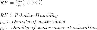
Relative humidity is expressed as a percentage. At 100% RH, condensation occurs, and at 0% RH, the air is completely dry.
HOW THE DHT11 WORKS
The DHT11 detects water vapor by measuring the electrical resistance between two electrodes. The humidity sensing component is a moisture holding substrate with electrodes applied to the surface. When water vapor is absorbed by the substrate, ions are released by the substrate which increases the conductivity between the electrodes. The change in resistance between the two electrodes is proportional to the relative humidity. Higher relative humidity decreases the resistance between the electrodes, while lower relative humidity increases the resistance between the electrodes.
The DHT11 measures temperature with a surface mounted NTC temperature sensor (thermistor) built into the unit.
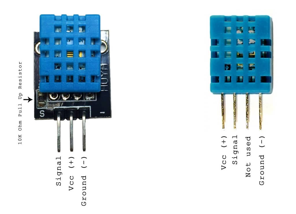
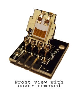
There are two different versions of the DHT11 you might come across. One type has four pins, and the other type has three pins and is mounted to a small PCB. The PCB mounted version is nice because it includes a surface mounted 10K Ohm pull up resistor for the signal line. Here are the pin outs for both versions:
With the plastic housing removed, you can see the electrodes applied to the substrate:
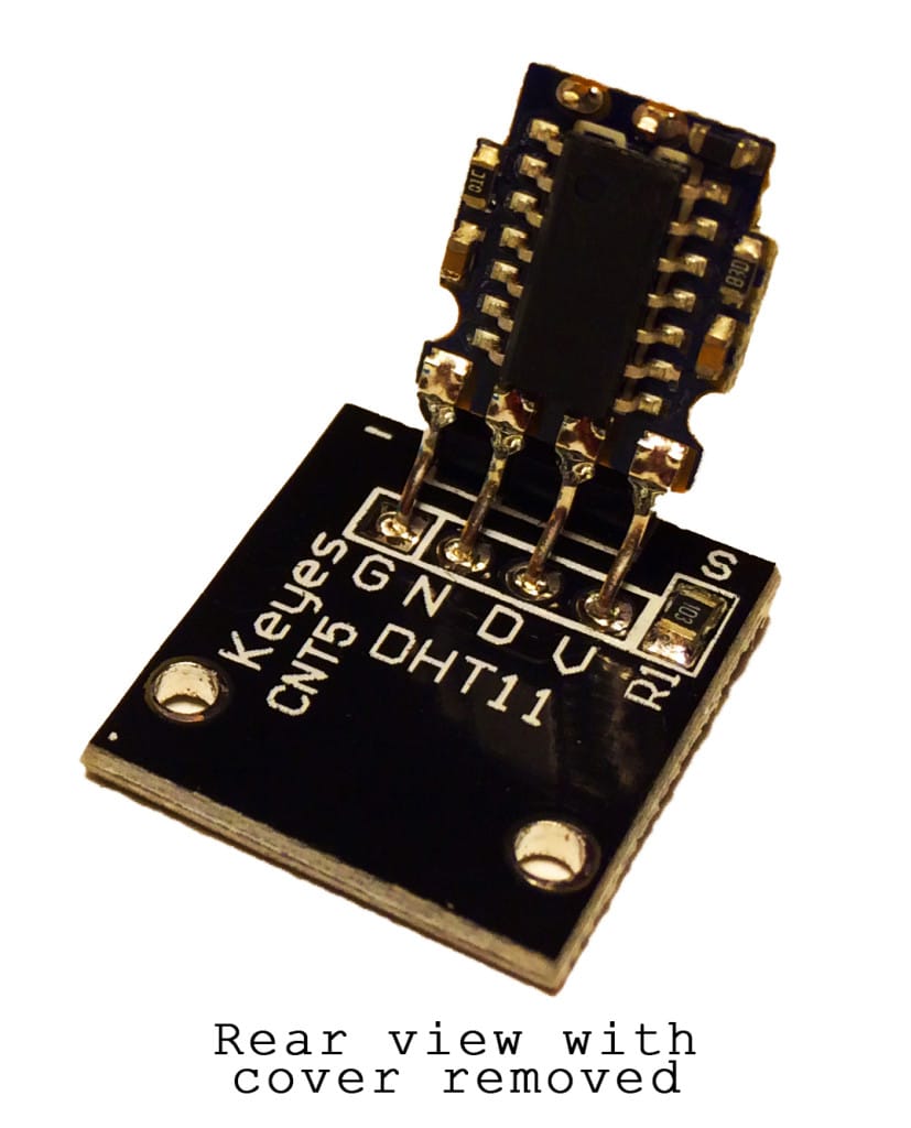
An IC mounted on the back of the unit converts the resistance measurement to relative humidity. It also stores the calibration coefficients, and controls the data signal transmission between the DHT11 and the Arduino:
Datasheet can be found here.
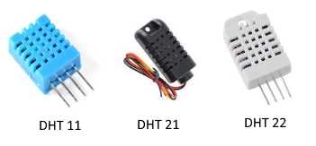
DHT 11, DHT 21 and DHT 22 have different specifications.
DHT11
Measurement Range 20-90%RH and 0-50 ℃
Humidity Accuracy ±5%RH
Temperature Accuracy ±2℃
Sensing period 1s
DHT 21
Measuring range 0-100% RH and 40 – 80℃
Accuracy humidity ±3%RH(Max ±5%RH)
Accuracy temperature < ±1℃
Sensing period Average: 2s
DHT 22
Measuring range 0-100%RH amd 40~80℃
Accuracy humidity ±2%RH(Max ±5%RH)
Accuracy temperature <±0.5℃
Sensing period Average: 2s
Signals and connections of DHT11 module
There are 3 : VCC (+5V), Data, GND (-)
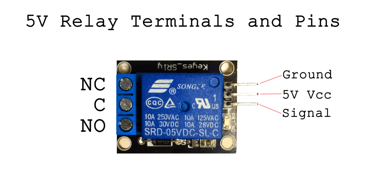
Signals and connections of 5V Relay module nad LM35 sensor.The SRD-05VDC-SL-C relay has three high voltage terminals (NC, C, and NO) which connect to the device you want to control. The other side has three low voltage pins (Ground, Vcc, and Signal) which connect to the Arduino.5V Relay PinoutNC: Normally closed 120-240V terminalNO: Normally open 120-240V terminalC: Common terminalGround: Connects to the ground pin on the Arduino5V Vcc: Connects the Arduino’s 5V pinSignal: Carries the trigger signal from the Arduino that activates the relayInside the relay is a 120-240V switch that’s connected to an electromagnet. When the relay receives a HIGH signal at the signal pin, the electromagnet becomes charged and moves the contacts of the switch open or closed.NORMALLY OPEN VS. NORMALLY CLOSEDThe relay has two different types of electrical contacts inside – normally open (NO) and normally closed (NC). The one you use will depend on whether you want the 5V signal to turn the switch on or turn the switch off. The 120-240V supply current enters the relay at the common (C) terminal in both configurations. To use the normally open contacts, use the NO terminal. To use the normally closed contacts, use the NC terminal.
The 5V Relay module has three high voltage terminals (NC, C, and NO) which connect to the device you want to control. The other side has three low voltage pins (GND (0V), VCC (+5V), and S(Signal)) which connect to the Arduino board.
- NC: Normally closed 120-240V terminal
- NO: Normally open 120-240V terminal
- C: Common terminal
Wiring
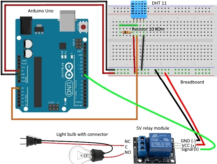
Let us build a HUMIDITY or TEMPERATURE controlled relay circuit that will turn on a light bulb when the humidity value of a DHT 11 sensor reaches 66% or temperature value reaches 25 degrees Celsius. DHT 11 OR 21 OR 22 sensors are really useful with 5V relays. You can use them to turn off a or turn on devices or power sockets depending on temperature or humidity values.
Make sure that the high voltage connections to the 5V relay module are very well secured.
Identify the hot power wire (red wire in the diagram above) in the cord leading to the light bulb and make a cut. Connect the side leading to the light bulb to the NO terminal of the 5V relay, and the side leading to the plug to the C terminal. This way the relay is on the hot side, and current is switched before it reaches the light bulb. It’s dangerous to put the relay on the neutral wire, since if the device fails current can still fault to ground when the relay is off.
The following picture shows the needed connections with the Arduino Uno
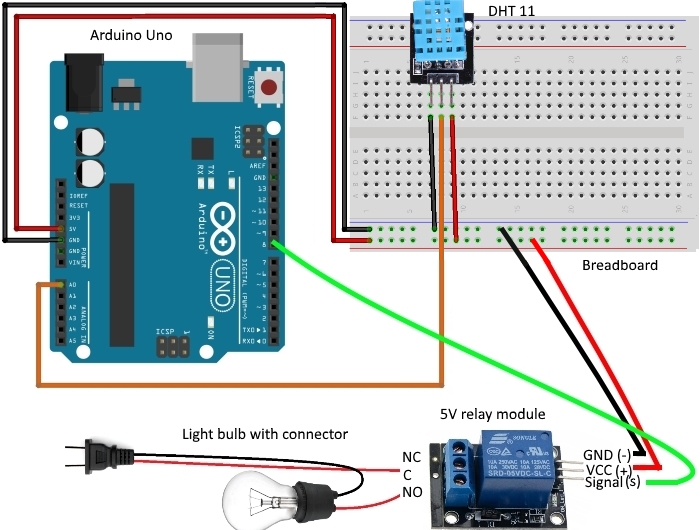
or
Step by Step instruction
- Plug your Adruino Uno board into your PC and select the correct board and com port
- Open up serial monitor and set your baud to 9600 baud
- Verify and upload the the sketch to your Adruino Uno
Libraries:
- See attachments on the begining of this project description
- Adafruit_Sensor library included.Download, unzip and add to libraries in our PC, for example C:\Users\toshiba\Documents\Arduino\libraries. This link you can find in Preferences of Adruino IDE program which installed in your PC.
- DHT-sensor library included. You will need to unzip and add the DHT-sensor-library-master library to libraries in your PC, for example C:\Users\toshiba\Documents\Arduino\libraries OR
- You can install it in Arduino IDE too: select Sketch-> Include library->Manage your libraries->type DHT in Filter your search line and you will see DHT sensor library by Adafruit->More info->select version->install
- If it will be problem with compilation – remove 2 files from the library – DHT_U.cpp and DHT_U.h.
link:https://acoptex.com/project/61/basics-project-011d-5v-relay-and-dht-11-21-22-sensor-humidity-or-temperature-controlled-relay-at-acoptexcom/