pH Meter using Arduino Uno
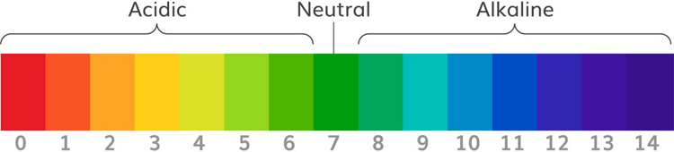
pH scale is used to measure the acidity and basicity of a liquid. It can have readings ranging from 1-14 where 1 shows the most acidic liquid and 14 shows the most basic liquid. 7 pH is for neutral substances that are neither acidic nor basic. Now, pH plays a very important role in our lives and it is used in various applications. For example, it can be used in a swimming pool to check the quality of water. Similarly, pH measurement is used in a wide variety of applications like agriculture, wastewater treatment, industries, environmental monitoring, etc.
In this project, we are going to make an Arduino pH Meter and learn how to measure the pH of a liquid solution using a gravity pH sensor and Arduino. A 16×2 LCD is used to show the pH value on the screen. We will also learn how to calibrate the pH sensor to determine the accuracy of the sensor. So let’s get started!
Required Components
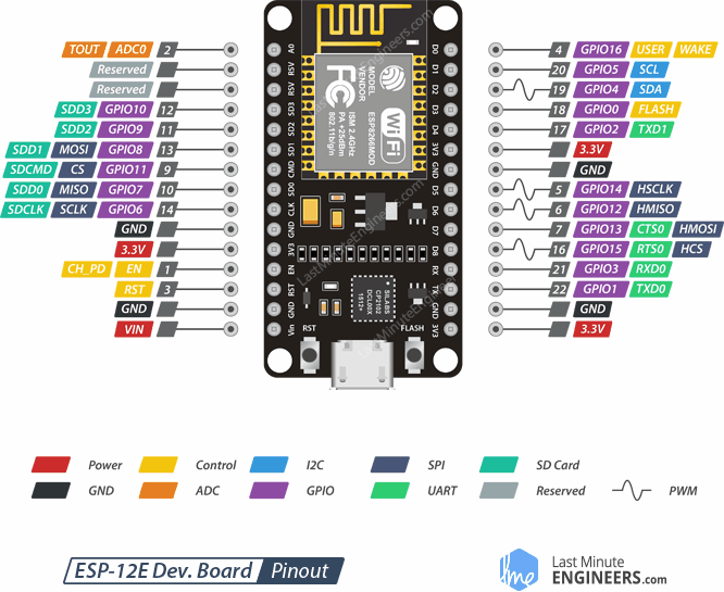
- Arduino Uno
- 16*2 Alphanumeric LCD
- I2C Module for LCD
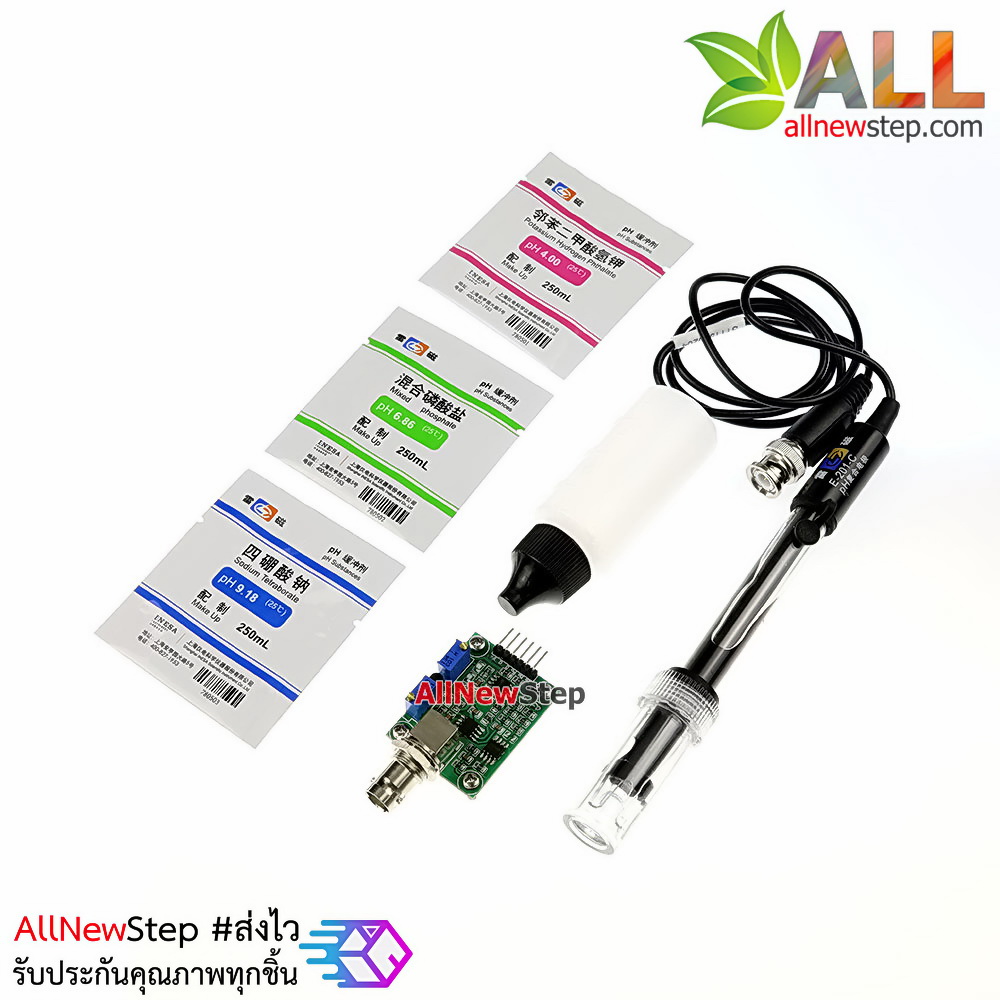
- Gravity Analog pH sensor
- Connecting wires
- Breadboard
What is pH Value?
The unit that we use to measure the acidity of a substance is called pH. The term “H” is defined as the negative log of the hydrogen ion concentration. The range of pH can have values from 0 to 14. A pH value of 7 is neutral, as pure water has a pH value of exactly 7. Values lower than 7 are acidic and values greater than 7 are basic or alkaline.
How Does Gravity Analog pH Sensor Work?
Analog pH sensor is designed to measure the pH value of a solution and show the acidity or alkalinity of the substance. It is commonly used in various applications such as agriculture, wastewater treatment, industries, environmental monitoring, etc. The module has an on-board voltage regulator chip which supports the wide voltage supply of 3.3-5.5V DC, which is compatible with 5V and 3.3V of any control board like Arduino. The output signal is being filtered by hardware low jitter.
Technical Features:
Signal Conversion Module:
- Supply Voltage: 3.3~5.5V
- BNC Probe Connector
- High Accuracy: ±0.1@25°C
- Detection Range: 0~14
PH electrode:
- Operating Temperature Range: 5~60°C
- Zero (Neutral) Point: 7±0.5
- Easy calibration
- Internal Resistance: <250MΩ

pH Signal Conversion Board:
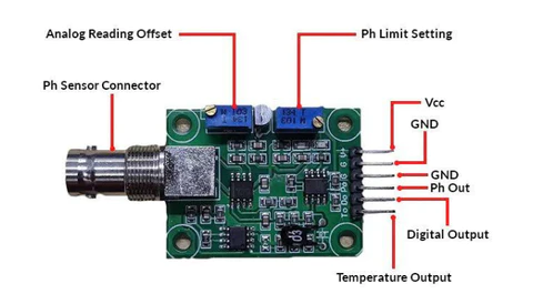
Pin Description:
V+: 5V DC input
G: Ground pin
Po: pH analog output
Do: 3.3V DC output
To: Temperature output
pH Electrode Construction:
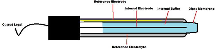
The construction of a pH sensor is shown above. The pH Sensor looks like a rod usually made of a glass material having a tip called “Glass membrane”. This membrane is filled with a buffer solution of known pH (typically pH = 7). This electrode design ensures an environment with the constant binding of H+ ions on the inside of the glass membrane. When the probe is dipped into the solution to be tested, hydrogen ions in the test solution start exchanging with other positively charged ions on the glass membrane, which creates an electrochemical potential across the membrane which is fed to the electronic amplifier module which measures the potential between both electrodes and converts it to pH units. The difference between these potentials determines the pH value based on the Nernst equation.
Nernst Equation:
The Nernst equation gives a relation between the cell potential of an electrochemical cell, temperature, reaction quotient and the standard cell potential. In non-standard conditions, the Nernst equation is used to calculate cell potentials in an electrochemical cell. The Nernst equation can also be used to calculate the total electromotive force (EMF) for a full electrochemical cell. This equation is used to calculate the PH value of a solution as well. The glass electrode response is governed by the Nernst Equation can be given as:E = E0 – 2.3 (RT/nF) ln Q Where Q= Reaction coefficient E = mV output from the electrode E0 = Zero offset for the electrode R = Ideal gas constant= 8.314 J/mol-K T = Temperature in ºK F = Faraday constant = 95,484.56 C/mol N = Ionic Charge
Arduino pH Meter Circuit Diagram
Circuit diagram for this Arduino pH meter project is given below:

Connection of pH Signal Conversion Board with Arduino:
The connection between Arduino and PH signal conversion board is shown in the table below.
| Arduino | PH Sensor board |
| 5V | V+ |
| GND | G |
| A0 | Po |

Programming Arduino for pH Meter
After successful hardware connections, now it’s time for programming the Arduino. The complete code for this pH meter with Arduino is given at the bottom part of this tutorial. The stepwise explanation of the project is given below.
The first thing to do in the program is to include all the required libraries. Here in my case, I have included “LiquidCrystal_I2C.h” library for using the I2C interface of an LCD display and “Wire.h” for using I2C functionality on Arduino.#include <Wire.h> #include <LiquidCrystal_I2C.h> LiquidCrystal_I2C lcd(0x27, 16, 2);
Next, the calibration value is defined, which can be modified as required to get an accurate pH value of solutions. (This is explained later in the article)float calibration_value = 21.34;
Inside setup (), LCD commands are written for displaying a welcome message on LCD. lcd.init(); lcd.begin(16, 2); lcd.backlight(); lcd.setCursor(0, 0); lcd.print(” Welcome to “); lcd.setCursor(0, 1); lcd.print(” Circuit Digest “); delay(2000); lcd.clear();
Inside loop(), read 10 sample analog values and store them in an array. This is required to smooth the output value.for(int i=0;i<10;i++) { buffer_arr[i]=analogRead(A0); delay(30); }
Then, sort the Analog values received in ascending order. This is required because we need to calculate the running average of samples in the later stage. for(int i=0;i<9;i++) { for(int j=i+1;j<10;j++) { if(buffer_arr[i]>buffer_arr[j]) { temp=buffer_arr[i]; buffer_arr[i]=buffer_arr[j]; buffer_arr[j]=temp; } } }
Finally, calculate the average of a 6 centre sample Analog values. Then this average value is converted into actual pH value and printed on an LCD display.for(int i=2;i<8;i++) avgval+=buffer_arr[i]; float volt=(float)avgval*5.0/1024/6; float ph_act = -5.70 * volt + calibration_value; lcd.setCursor(0, 0); lcd.print(“pH Val:”); lcd.setCursor(8, 0); lcd.print(ph_act); delay(1000); }
Calibration of pH Electrode
Calibration of the PH electrode is very important in this project. For this, we need to have a solution whose value is known to us. This can be taken as the reference solution for the calibration of the sensor.
Suppose, we have a solution whose PH value is 7 (distilled water). Now when the electrode is dipped in the reference solution and the PH value displayed on LCD is 6.5. Then to calibrate it, just add 7-6.5=0.5 in the calibration variable “calibration_value” in the code. i.e. make the value 21.34 + 0.5=21.84. After making these changes, again upload the code to Arduino and recheck the pH by dipping electrode in the reference solution. Now LCD should show the correct pH value i.e. 7 (Little variations are considerable). Similarly, adjust this variable to calibrate the sensor. Then check for all other solutions to get the exact output.
Testing Arduino pH Tester
We have tried this Arduino pH meter by dipping it into pure water and Lemon water, you can see the result below.
Pure Water:

Lemon Water:

This is how we can build a pH sensor using Arduino and can use it to check the pH level of various liquids.
Complete code and demonstration Code1 are given below.
#include <Wire.h>
#include <LiquidCrystal_I2C.h>
LiquidCrystal_I2C lcd(0x27, 16, 2);
float calibration_value = 21.34;
int phval = 0;
unsigned long int avgval;
int buffer_arr[10],temp;
void setup()
{
 Serial.begin(9600);
  lcd.init();
  lcd.begin(16, 2);
  lcd.backlight();
  lcd.setCursor(0, 0);
  lcd.print("   Welcome to      ");
  lcd.setCursor(0, 1);
  lcd.print(" Circuit Digest    ");
  delay(2000);
  lcd.clear();
}
void loop() {
 for(int i=0;i<10;i++)
 {
 buffer_arr[i]=analogRead(A0);
 delay(30);
 }
 for(int i=0;i<9;i++)
 {
 for(int j=i+1;j<10;j++)
 {
 if(buffer_arr[i]>buffer_arr[j])
 {
 temp=buffer_arr[i];
 buffer_arr[i]=buffer_arr[j];
 buffer_arr[j]=temp;
 }
 }
 }
 avgval=0;
 for(int i=2;i<8;i++)
 avgval+=buffer_arr[i];
 float volt=(float)avgval*5.0/1024/6;
 float ph_act = -5.70 * volt + calibration_value;
 lcd.setCursor(0, 0);
 lcd.print("pH Val:");
 lcd.setCursor(8, 0);
 lcd.print(ph_act);
 delay(1000);
}
From:https://circuitdigest.com/
Code2: CODING_PH_SENSOR_CALIBRATION.ino (Website: https://www.mybotic.com.my/)
#define OFFSET

int pH_Value;
float Voltage;

void setup()
{
  Serial.begin(9600);
  pinMode(pH_Value, INPUT);
}

void loop()
{
  pH_Value = analogRead (A0);
  Voltage = pH_Value * (5.0/1023.0);
  Serial.println(Voltage);
  delay(500);
}
Code3: CODING_pH_meter.ino (Website: https://www.mybotic.com.my/)
#define PH_OFFSET -1.00 //if there have offset

#define SensorPin A0        // the pH meter Analog output is connected with the Arduino’s Analog
unsigned long int avgValue;  //Store the average value of the sensor feedback
float b;
int buf[10],temp;

void setup()
{
  pinMode(13,OUTPUT);
  Serial.begin(9600);
  Serial.println("Ready");    //Test the serial monitor
}
void loop()
{
  for(int i=0;i<10;i++)       //Get 10 sample value from the sensor for smooth the value
  {
    buf[i]=analogRead(SensorPin);
    delay(10);
  }
  for(int i=0;i<9;i++)        //sort the analog from small to large
  {
    for(int j=i+1;j<10;j++)
    {
      if(buf[i]>buf[j])
      {
        temp=buf[i];
        buf[i]=buf[j];
        buf[j]=temp;
      }
    }
  }
  avgValue=0;
  for(int i=2;i<8;i++)                      //take the average value of 6 center sample
    avgValue+=buf[i];
  float phValue=(float)avgValue*5.0/1024/6; //convert the analog into millivolt
  phValue=3.5*phValue;                      //convert the millivolt into pH value

  phValue = phValue + PH_OFFSET;

  Serial.print("    pH:");
  Serial.print(phValue,2);
  Serial.println(" ");
  digitalWrite(13, HIGH);
  delay(800);
  digitalWrite(13, LOW);
}
Code4:
#define Offset 0.00
void setup() {
// initialize serial communication at 9600 bits per second:
Serial.begin(9600);
}
// the loop routine runs over and over again forever:
void loop() {
// read the input on analog pin 0:
int sensorValue = analogRead(A0);
// print out the value you read:
float phValue=sensorValue*5.0/1024/6; //convert the analog into millivolt
phValue=3.5*phValue+Offset;
//float pHvolt = phValue*(5.0/1024);
//phValue= -5.6*pHvolt + 21.188; //equation from datasheet
Serial.println(sensorValue);
delay(200); // delay in between reads for stability
}
Measure pH with a low-cost Arduino pH sensor board (www.e-tinkers.com)
Tuned to 2.5V for the 7 Ph baseline
I recently bought an Arduino pH sensor kit for measuring pH value of my hydroponic setup, it cheap but has very little information/document on how to use it, so I decided to figure it out myself on how it works and how to use it.
Popular pH measurement kits for Arduino
If you search for pH sensor with Arduino on Internet, you are likely see 3 major commercially available or mass-produced solutions:
Atlas Scientific offers high quality and well-designed sensor kit for pH measurement. It Gravity analog pH Kit consists of a consumer-grade pH sensor and interface board, plus 3 package of calibration buffer solutions will cost $65.00. Atlas Scientific hardware is high quality but doesn’t seems to be open-sourced.
DFRobot also has a solution with the same name Gravity (why?) as Atlas Scientific. its version 1 Gravity: Analog pH Sensor Kit consists of pH probe plus the sensor board and is priced at $29.50. There is a version 2 of Gravity: Analog pH Sensor Kit which comes with the board with enhanced design at $39.50 by including buffer solutions and mounting screws for the board. DFRobot published its schematic, PCB layout and Arduino code for version 1 on its website and github under GPL2 license. But it only publish the PCB layout for version 2 without schematic, so I don’t know what exactly was enhanced in the design for the version 2.
The third commonly available pH sensor kit for Arduino that you see almost in every e-commerce marketplaces such as Taobao, AliExpress and Amazon is this “mystery” pH sensor kit that I bought. You can find it at as low as $17.00 for a pH probe with the sensor board. It is “mystery” because it seems that there are multiple Chinese manufacturers producing the same board but I can’t really find out which company actually own the design. I bought it anyway with the thinking that if I could understand how the pH probe works and with a little bit of “reverse-engineering” of the circuit design to help me to have better understanding of the circuitry, then I should be able to figure out on how to make it work. This fits my tinker spirit well…
Other than those three commonly available pH sensor kits, there are others available in the market, but they are relatively niche with limited distribution.
If you are interested on pH measurement or pH sensor board, you might to read further on A review on Seeed Studio pH and eC sensor kits – Part 1″.
How pH probe work electronically?
A pH probe consists of two main parts: a glass electrode and a reference electrode as shown in the picture below. I’m not very good at chemistry, so I won’t try to explain it that way, this pH theory guide provides very comprehensive explanation about the theory behind. In the nutshell, pH is determined essentially by measuring the voltage difference between these two electrodes.
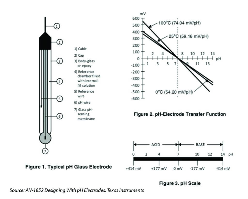
The pH probe is a passive sensor, which means no excitation voltage or current is required. It produces a voltage output that is linearly dependent upon the pH of the solution being measured. An ideal pH probe produces 0v output when pH value is at 7, and it produces a positive voltage (a few hundred mili-volts) when pH value go down, and a negative voltage level when pH value go up, causing by the hydrogen irons forming at the outside (and inside) of the membrane glass tip of the pH probe when the membrane comes into contact with solution. The source impedance of a pH probe is very high because the thin glass bulb has a large resistance that is typically in the range of 10 MΩ to 1000 MΩ. Whatever measurement circuit connect to the probe requires to be high-impedance in order to minimise the loading effect of the circuit.
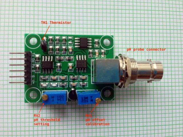
Hardware – The pH sensor board explained
The pH sensor board that I bought came without any user guide, schematic or example code. I asked the small Chinese vendor for information but in vain. I decided to “reverse-engineering” the schematic diagram but eventually I find the schematic diagram at the attachment of this Arduino forum discussion. The pH sensor board can be divided into 3 different sections based on its functionality. I colour the three key sections with different color for discussion here.

pH Measurement Circuit
The light green section with the TLC4502 high-impedance operation amplifier basically consists of a voltage divider and a unity-gain amplifier. The pH output(Po) provided an analog output for pH measurement. As pH probe swing between positive and negative voltage, and since TLC4502 is operate with single power source, half of the TLC4502 is used as a voltage divider to provide a reference voltage of 2.5v to “float” the pH probe input so that the output of Po will be +/-2.5v based on pH value. A potentiometer RV1 is used for calibration purpose that I will further discuss later. This part of the circuit is well-designed and it is all it needed for measuring the pH value. The other parts of the board in my opinion are not well designed and sort of in the category of “nice-to-have” and not essential.
pH Threshold Detection Circuit
The yellow section provides a pH threshold detection/notification circuit. For example, you could adjust the potentiometer RV2 so that when pH level reach a threshold level (e.g. say 7.5), the RED LED D1 will be turned on (Digital output Do changed from high to low). Alternatively, you could use it to detect the lower pH level threshold, say, when pH value is below 5.5, the RED LED will be turned off and Do changes from low to high. But you can’t set both lower and upper thresholds with this circuit. In my opinion, it will be easier to just use software solution than this hardware solution for threshold detection.
Temperature Reading Circuit
The light blue/cyan section of the board consists of 1 and a half LM358 OpAmp, and provides an analog reading at To. U2B of LM358 acts as a not so accurate voltage divider and provides a voltage reference of 2.5v to a Wheatstone bridge that consists of R13 – R15 and a thermistor TH1. The U3A behave as an differential OpAmp, the output is then pass through a low-pass filter and further amplified by a non-inverting OpAmp U3B. This entire circuit has nothing to do with pH measurement, at least not directly. I will talk about this toward the end of this article.
The sole reason for measuring temperature in the context of measuring pH value is because that pH curve slope changes when temperature change between 0 to 100 degree Celsius. It is therefore important to measure the temperature of the solution, and add temperature compensation factor into the pH calculation.
One thing interesting is that all the manufacturers for this board design that I saw in the market had the thermistor solder on the board instead of having a water-proof thermistor probe like the one that I described in my my previous post. By soldering thermistor on-board, that means the thermistor is measuring ambience temperature near the board instead of the temperature of the solution where pH was measured, this simply doesn’t make sense. This makes me think that all those Chinese manufacturers are simply copying the design from a circuit diagram or reverse-engineering without understanding the purpose of having the thermistor for temperature measurement in the context of pH measurement application.
Now I studied and understand the circuit diagram, it is time to calibrate the pH sensor and write some code for measuring the pH value!
How to calibrate the pH sensor?
As discussed previously that by design the pH probe oscillates between negative and positive values. When the pH reading is at 7.0, the pH output is offset by 2.5v so that both negative and positive values generated by the pH probe can be represented as positive values in full range, this means that when pH is at 0, the Po would be at 0v, and when pH is at 14, the Po would be at 5v.
In order to make sure that when pH is at 7.0, we can calibrate the reading to make sure that Po will be at 2.5v by disconnecting the probe from the circuit and short-circuiting the inner pin of the BNC connector with the outer BNC ring. With a multimeter measure the value of Po pin and adjust the potentiometer to be 2.5V. Don’t worry if you don’t have a multimeter, you can write an Arduino sketch to read the analog input by connecting the Po to analog input A0 of the Arduino.
ph_calibrate.ino#include <Arduino.h> const int adcPin = A0; void setup() { Serial.begin(115200); } void loop() { int adcValue = analogRead(adcPin); float phVoltage = (float)adcValue * 5.0 / 1024; Serial.print(“ADC = “); Serial.print(adcValue); Serial.print(“; Po = “); Serial.println(phVoltage, 3); delay(1000); }
Connect Po to Aanalog input A0 on Arduino, and G to Arduino GND. Run the Arduino sketch, and open the Serial Monitor of Arduino IDE to observe the reading, slowly adjust the potentiometer RV1 (the one near the BNC connector on the board) until the Po reading equal to 2.50v.
This is assuming that all the pH probe are equal and will produce exactly 0v at pH reading of 7.0, but in reality all probes are slightly different from each other, especially for consumer-grade pH probe. Temperature also affect the reading of pH sensor slightly, so the better way is to use a pH buffer solution of pH=7.0 to calibrate the probe. All the buffer solution will have the temperature compensation information on its package that you could factor-in for your calibration.
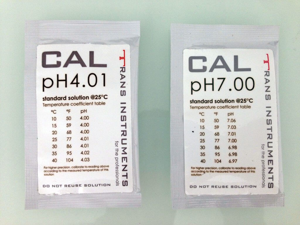
pH buffer packages for calibration purpose available in liquid form or in powders form, liquid pack is easy to use but powders pack is good for storage. These solutions are sold in different values but the most common are pH 4.01, pH 6.86 and pH 9.18.
pH values are relatively linear over a certain range (between ph 2 to ph 10), we need two calibration points to determine the linear line, and then derives the slope of the line so that we could calculate any pH value with a given voltage output (see Figure 2 chart above). What value of pH buffer to use for this second calibration depends on your application, if your application is for measuring acidic solution, use buffer solution for ph=4.01 for the second calibration; buf if your application is mostly for measuing basic/alkanine solution, use buffer solution of ph=9.18 for the second calibration. In my case, as hydroponic for vegetable grow tends to be slightly acidic with ph ranging between 5.5 – 6.5, I use ph=4.01 buffer solution for my calibration.
To avoid cross contamination, dip the probe in distill water for a couple of minites before dipping it in different buffer solutions. For increase the accuracy, let the probe stay in the buffer solution for a couple of minutes before taking the reading as the result.
Use the same Arduino sketch to get the voltage reading for pH=4.01, and write down the voltage value, in my case, the voltage is 3.06 @ pH=4.01. The voltage readings at ph of 4.01 Vph4 and at pH of 7.0 Vph7 allows us to draw a straight line, and we can get the Voltage change per pH value m as:m = (ph7 – ph4) / (Vph7 – Vph4) / m = (7 – 4.01) / (2.5 – 3.05) m = -5.436
So the pH value at any voltage reading at Po can be derived with this formula:pH = pH7 – (Vph7 – Po) * m i.e. pH = 7 – (2.5 – Po) * m
Measure pH value
With the formula, we can create the Arduino sketch to measure the pH value based on the voltage reading at the Po.#include <Arduino.h> const int adcPin = A0; // calculate your own m using ph_calibrate.ino // When using the buffer solution of pH4 for calibration, m can be derived as: // m = (pH7 – pH4) / (Vph7 – Vph4) const float m = -5.436; void setup() { Serial.begin(115200); } void loop() { float Po = analogRead(adcPin) * 5.0 / 1024; float phValue = 7 – (2.5 – Po) * m; Serial.print(“ph value = “); Serial.println(phValue); delay(5000); }
How about Temperature Measurement?
As I mentioned before it doesn’t make sense to measure the ambience temperature near the PCB, so the first thing I did is de-solder the on-board thermistor and replace it with one of those water-prove thermistors.
A Wheatstone Bridge circuit is nothing more than two simple series-parallel arrangements of resistances connected between a reference voltage supply and ground producing zero voltage difference between the two parallel branches when balanced. When one of the arm of the resistance arrangements consists of a thermistor, its resistance changes as temperature changed, causing the imbalance of two resistance arms and a voltage difference developed between the two parallel branches in according to the change of the thermistor resistance which is directly related to the change of the temperature.
Specifically to this circuit, the voltage reference is provided by U2B which formed a voltage divider and produce a reference voltage (let’s called it Vref) of 2.5V at pin 7 of U2B. According to the characteristics of thermistor, the thermistor will have a resistance of 10k-ohms at temperature of 25 degree Celsius. The Wheatstone Bridge will be balanced and the output voltage Vd of the Wheatstone Bridge at the terminals of resistors R16 and R18 will be zero and will swing above and below 0 volt when temperature changes. The Vd is then amplified by U3A which seems to be a differential amplifier, the U3B is a typical non-inverting amplifier. As I’m not quite sure about the gain of U3A so I decided to ask at Electrical Engineering StackExchange, and I got my questions answered within an hour. The circuit has a total gain of 14.33 when the thermistor is at 10k (i.e. when temperature is at 25 degree Celsius). However, the gain of U3A will change when the thermistor resistance change, obviously this is not a very good design.
I also got confirmed my suspicion that there is a missing 20k resistor between between pin 3 of U3A and ground on the circuit diagram, interestingly the circuit board is designed to have this resistor, but where the resistor is supposed to be is left empty (why?). Further inspect the circuit I noticed that the R12 on the board is actually having a value of 51.1k instead of 100k as shown in the circuit diagram. So the over gain will be 1.33+5.11+1=7.44.
We can derive the Vd based on the measured voltage of To, and further derive the value of resistance of TH1 at the temperature where To is measured: Vd = To / 7.44 Vd = Vref * (R14 / (R14 + R15)) – Vref * (R13 / (R13 + TH1))
Absolute temperature T based on Steinhart–Hart equation for thermistor calculation can then be derived from: T = 1 / (1/To + 1/B * ln(TH1/Ro))
Where:
T is the absolute temperature to be measured in Kelvin;
To is the reference temperature in Kelvin at 25 degree Celsius;
Ro is the thermistor resistance at To;
B is Beta or B parameter = 3950, provided by manufacturer in their specification.
In theory, the primary benefit of Wheatstone Bridge circuit is its ability to provide extremely accurate measurements in contrast with a simple voltage divider, as a voltage divider is often affected by the loading impedance of the measuring circuit. In actual application, the accuracy of the Wheatstone Bridge is highly depend on the precision of the resistors used to form the Wheatstone Bridge, the precision of voltage reference as well as the circuit that connected to the Wheatstone Bridge. Although I figured out the formula on how to measure the temperature, I did not write the code to calculate the temperature, as the gain of U3A will vary as the value of the thermistor varies in according to the temperature. This make the reading result almost unpredictable and I will probably not use this circuit for measuring the water temperature without further modifying the design.
In Summary
Overall, this pH sensor board has a good pH measurement circuit design, the rest parts of the circuit are quite useless and a little bit over-engineered. By eliminating the bad part of the circuit design and kept the good part, it could be simpler and maybe slightly cheaper than current design for a pH sensor board.