One of the nice things about the ESP8266 is that it has a fair amount of GPIO pins to work with. You won’t have to juggle or multiplex your IO pins. However, there are a few things to keep in mind, so please read the pinout carefully.
ESP8266 Peripherals and I/O
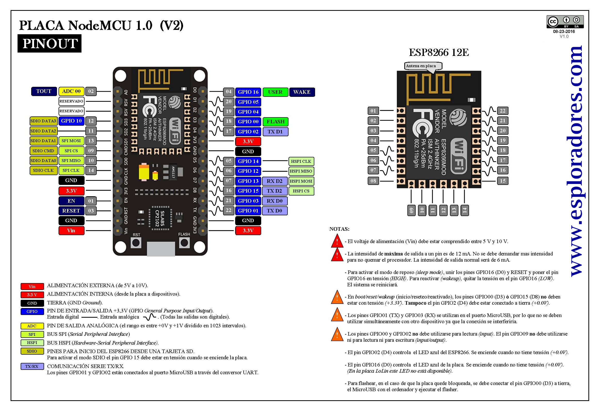
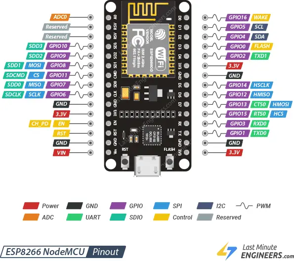
The ESP8266 NodeMCU has 17 GPIO pins in total, which are broken out to the pin headers on both sides of the development board. These pins can be assigned a variety of peripheral duties, including:
| 1 ADC channel | 1 channel of 10-bit precision SAR ADC |
| 2 UART interfaces | 2 UART interfaces with with support for flow control |
| 4 PWM outputs | 4 PWM pins to control things like motor speed or LED brightness |
| 2 SPI and 1 I2C interfaces | Two SPI and one I2C interfaces for connecting various sensors and peripherals |
| I2S interface | One I2S interface for adding sound to your project |
Thanks to the ESP8266’s pin multiplexing feature, which allows multiple peripherals to share a single GPIO pin. Meaning, a single GPIO pin can perform functions such as I2C, I2S, UART, and PWM, etc.
For extensive information about the ESP8266, please refer to the datasheet.
ESP8266 Pinout
The ESP8266 NodeMCU has 30 pins in total. For convenience, pins with similar functionality are grouped together. The pinout is as follows:

Let’s take a closer look at the ESP8266 pins and their functions one by one.
GPIO Pins
The ESP8266 NodeMCU has 17 GPIO pins that can be assigned different functions by programming the appropriate registers. Each GPIO can be configured with internal pull-up or pull-down, or set to high impedance.

Which ESP8266 GPIOs are safe to use?
Although the ESP8266 has a lot of pins with various functions, some of them may not be suitable for your projects. The table below shows which pins are safe to use and which pins should be used with caution.
– Your top priority pins. They are perfectly safe to use.
- – Pay close attention because their behavior, particularly during boot, can be unpredictable. Use them only when absolutely necessary.
- – It is recommended that you avoid using these pins.
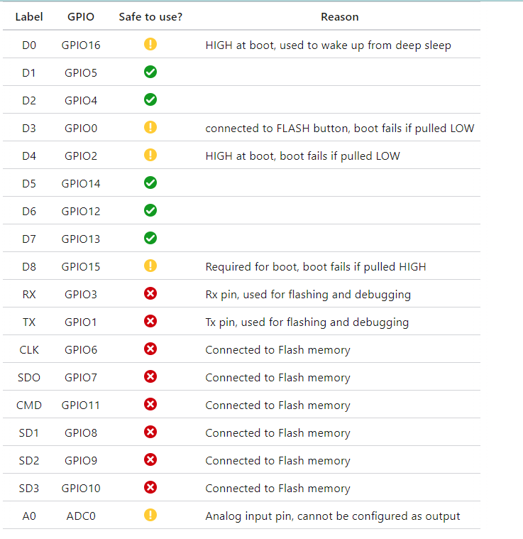
The image below shows which GPIO pins can be used safely.

ADC Pins
The ESP8266 is embedded with a 10-bit precision SAR ADC, which means it can detect 1024 (2^10) discrete analog levels. In other words, it will convert input voltages ranging from 0 to 3.3V (operating voltage) into integer values ranging from 0 to 1024. This results in a resolution of 3.3 volts / 1024 units, or 0.0032 volts (3.2 mV) per unit.

The following two measurements can be implemented using ADC. However, they cannot be implemented at the same time.
- Measure the power supply voltage of VDD3P3 (Pin3 and Pin4).
- Measure the input voltage of A0.
SPI Pins
ESP8266 features two SPIs (SPI, and HSPI) in slave and master modes. These SPIs also support the general-purpose SPI features listed below:
- 4 timing modes of the SPI format transfer
Up to 80 MHz and the divided clocks of 80 MHz
Up to 64-Byte FIFO

It is possible to use SPI on any pins by ‘bitbanging’.
I2C Pins
The ESP8266 doesn’t have hardware I2C pins, but it can be done by ‘bitbanging’. It works quite well, and the ESP8266 is fast enough to match ‘Arduino level’ speed.
By default, GPIO4 (SDA) and GPIO5 (SCL) are used as I2C pins to make it easier for people using existing Arduino code, libraries, and sketches.
However, you can use any other two GPIO pins as I2C pins by calling wire.begin(SDA, SCL) in the Arduino IDE.

UART Pins
The ESP8266 has two UART interfaces, UART0 and UART2, that support asynchronous communication (RS232 and RS485) at up to 4.5 Mbps.
- UART0 (TXD0, RXD0, RST0, and CTS0 pins) is used for communication.
- UART1 (TXD1 pin) only features a data transmit signal and is typically used for printing logs.

RXD0 and TXD0 are the serial control and bootloading pins. They are primarily used for communicating with the ESP module.
Therefore, you should use caution when using these since they are connected through to the USB-to-serial converter and will therefore receive USB traffic.
PWM Pins
All of the ESP8266’s GPIO pins, from GPIO0 to GPIO15, can be programmed to generate pulse width modulated (PWM) outputs.

On the ESP8266, the PWM signal has a 10-bit resolution, and the PWM frequency range is adjustable between 1000 μs and 10000 μs, i.e., between 100 Hz and 1 kHz.
SDIO Pins
The ESP8266 has one slave SDIO (Secure Digital Input/Output Interface) for connecting SD cards. SDIO v1.1 (4-bit 25 MHz) and SDIO v2.0 (4-bit 50 MHz) are supported.

Power Pins
The VIN pin can be used to directly power the ESP8266 and its peripherals, if you have a regulated 5V power supply.
The 3V3 pin is the output from the on-board voltage regulator; you can get up to 600mA from it.
GND is the ground pin.

Interrupt Pins
All GPIOs can be configured as interrupts, except GPIO16.
Control Pins
The EN (a.k.a. CH_PD or Chip Power Down) pin is the enable pin for the ESP8266, pulled high by default. When pulled HIGH, the chip is enabled; when pulled LOW, the chip is disabled.
The RST pin is the reset pin for the ESP8266, pulled high by default. When pulled down to ground momentarily it will reset the ESP8266. It is equivalent to pressing the on-board RST button.
The FLASH pin is used by the ESP8266 to determine when to boot into the bootloader. If the pin is held low during power-up it will start bootloading! It is equivalent to pressing the on-board FLASH button.
The WAKE pin is used to wake the ESP8266 from deep sleep.